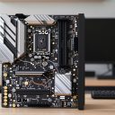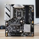

PC front panel connectors are the small cables from your case that plug into pin headers along the motherboard edge. They handle the power and reset buttons, the status lights, the front USB ports, and the headphone and microphone jacks. The switch cables have no polarity and can go either way, the LED cables do have a positive and negative side, and the USB and audio cables are shaped so they only fit the right header in one direction.
This 2026 guide explains each connector, how to identify it, and how to plug it in safely. Header layouts and labels differ between motherboard models, so use the diagrams here as a general map and always confirm the exact pin positions in your motherboard manual before connecting anything.
The Front Panel Header: Power, Reset, and LEDs
The most confusing group is a block of loose single-pin or two-pin connectors that all plug into one shared header, usually labeled something like system panel, front panel, or a similar name. Each connector is labeled on the cable itself, and the motherboard prints or documents which pins belong to each one.
Power switch
The power switch cable, often labeled power SW, works like a momentary button that briefly connects two pins. It has no polarity, so it does not matter which way the two-pin plug goes on, as long as it sits on the correct pair of pins.
Reset switch
The reset cable behaves the same way as the power switch. Some cases omit it, and some builders skip it entirely. Plugging it in is optional, though connecting it restores the case button.
Power LED
The power light shows that the system is on. It has a positive and negative side, so check the markings on the plug and the header diagram. If the light does not turn on, the usual fix is flipping the plug over. A reversed LED will not cause damage in typical cases, but it will not light.
Drive activity LED
The storage activity light blinks during disk activity. It also has polarity, and the same flipping trick applies if the light stays dark. Some modern cases and boards behave differently with this light, so it may not blink under every storage type.
Case speaker
Older boards used a small internal speaker for startup beep codes. Some cases include one, and some motherboards have it built in. If your board supports it, the speaker can be useful for diagnosing boot problems.
Reading the Header Layout
The front panel header is usually a block of pins in two rows, with one pin position intentionally missing or blocked to help orient the connector. Confusion often comes from the fact that the pin order is not the same on every board.
Check the silkscreen and the manual
Most boards print small labels next to the header, and the manual includes a clearer diagram. Match each cable label to the pin pair on that diagram, and plug in one cable at a time.
Use the adapter block if provided
Some motherboards include a small adapter that lets you plug all the front panel cables into it first and then press the whole block onto the header at once. If yours has one, it reduces mistakes and makes tight spaces easier.
Work with good light
These pins are tiny, and the labels are small. A flashlight and a steady hand help, and taking a photo of the header before you start gives you a reference to compare against.
Connector Quick Reference
| Connector | Typical cable label | Polarity matters? | Notes |
|---|---|---|---|
| Power switch | Power SW | No | Two pins, momentary contact |
| Reset switch | Reset SW | No | Optional on many builds |
| Power LED | Power LED plus and minus | Yes | Flip the plug if it stays dark |
| Drive activity LED | HDD LED | Yes | May not blink with every storage type |
| Front USB 2.0 | USB 2.0 | Keyed header | Supports two ports per header |
| Front USB 3.x | USB 3.0 | Keyed header | Wide connector, usually two ports |
| Front USB-C | USB Type-C | Keyed header | Needs a matching header on the board |
| Front audio | HD Audio | Keyed header | Headphone and microphone jacks |
USB Headers: 2.0, 3.x, and Type-C
The USB connectors are bigger than the switch and LED plugs, and they are shaped to stop you from using the wrong one. Even so, forcing a mismatch can bend pins, so never push a connector that does not slide in smoothly.
USB 2.0 header
The older style uses a block of pins in two rows with one pin missing for orientation. One header usually supports two front ports. Boards often provide a couple of these headers for the case and other accessories.
USB 3.x header
This is a wider connector with more pins and a notch that aligns it. It supports faster data transfer and typically serves two ports. Plugging a USB 3.x cable into a USB 2.0 header is not possible because the shapes differ, and the reverse should never be forced.
USB Type-C front panel header
If your case has a front Type-C port, it uses a compact keyed connector that plugs into a matching header on the motherboard. Not every board has one, so check the specifications before choosing a case with a front Type-C port. The speed supported depends on the board and header, so confirm it in the manual.
Front Audio Header
The front audio cable, usually labeled HD Audio, brings the headphone and microphone jacks to the motherboard. It uses a keyed connector with one pin position blocked, and the header is typically located along the bottom edge of the board near the audio chip.
HD Audio versus older AC97
Modern cases and boards use the HD Audio standard. Some older cases still include an older cable, and mixing the two can give no sound or odd behavior, so use the HD Audio cable if you have the choice.
If the front jacks are silent
Check that the connector is fully seated and that the audio driver software has the front jack enabled. In many setups, the audio control panel needs to detect the device, and the output may need to be selected manually.
Safe Installation Steps
- Power off the PC, switch off the power supply, and unplug the power cable.
- Touch a bare metal part of the case to discharge static electricity.
- Open your motherboard manual to the front panel header section and keep it nearby.
- Connect the power switch cable first, matching the label to the diagram.
- Connect the reset switch, then the two LED cables, paying attention to plus and minus markings.
- Plug in the USB 3.x and USB 2.0 cables to their keyed headers, then add USB Type-C and HD Audio cables if your case has them.
- Gently check that no connector is half-seated or sitting on the wrong pins, then route the cables behind the motherboard tray where possible.
- Power on the system and confirm the button starts it and the LEDs and front ports work.
Before You Close the Case
- Every connector is seated fully on the correct pins.
- LED plugs match the polarity markings, or you plan to flip them if a light stays dark.
- USB and audio connectors were pushed in straight with no bent pins.
- Cables are routed away from fans and the processor cooler.
- The case button powers on the system and front ports are detected.
Common Mistakes
- Guessing the pin order instead of checking the motherboard manual for the exact header layout.
- Forcing a connector that does not fit, which can bend or break pins.
- Confusing a fan or lighting header with a USB or front panel header because they look similar.
- Plugging the power switch into the reset pins, then wondering why the power button seems to do nothing.
- Skipping the LED cables because the system turns on, then forgetting that the lights can be fixed later by flipping the plug.
Related guides
- Aio Liquid Coolers For High Performance Gaming
- How To Lower Input Delay In Competitive Shooters
- Wireless Gaming Headsets Under 100 For Pc
Frequently Asked Questions
Does it matter which way the power switch cable goes?
No, the power switch is a simple momentary contact without polarity. It only matters that the plug sits on the right pair of pins.
Why is my case LED not lighting up?
The most common reason is reversed polarity. Power off, flip the plug over, and try again, and also confirm the plug is on the right pins in the manual diagram.
Can I use a USB 3.0 case cable on a board without a matching header?
Not directly, since the connector shapes differ. Check your motherboard specifications before buying a case, and consult the case maker about any supported adapters.
What if my power button does nothing?
Recheck that the power switch cable is on the correct pins, and confirm other power cables are secure. Some builders briefly touch the two power switch pins with an insulated tool to see whether the board starts, following the manual and taking care not to touch anything else.