
To read a motherboard manual, start with the quick installation or layout diagram, then use the specifications and the expansion slot table to see what shares bandwidth, and match each cable to its header using the connector pinout pages. The manual is the only reliable source for which header is which on your exact board, because labels, pin counts and sharing rules differ between models.
This guide walks through the sections of a typical manual, how to decode the abbreviations printed on the board, and a safe order for connecting parts in 2026. Naming and layouts vary by manufacturer and generation, so always confirm details in the manual that matches your exact model and revision, which you can usually download from the manufacturer’s support page. When in doubt about a connector, stop and check rather than forcing it.
Find the Right Manual First
The correct document saves most confusion. Look at the board itself for the model name printed near the processor socket or between the PCIe slots, and note any revision number on the board. Then download the PDF from the manufacturer’s site rather than a third-party mirror.
Quick Guide Versus Full Manual
Boards often ship with a short quick guide. It shows basic placement but leaves out sharing rules, header pinouts and BIOS details. Use it for orientation and the full manual for decisions. A search function inside the PDF helps you jump to abbreviations quickly.
BIOS Version and Compatibility
Processor support lists mention minimum BIOS versions. If you plan to install a newer processor on an older board, check this list before building, because the board may need an update first. The manual and the support page describe the update process.
Layout Diagram and Block Diagram
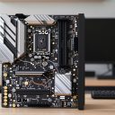
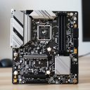
The layout diagram labels every slot and header on the board. A block diagram, if included, shows how lanes connect to the processor and chipset, which explains why some ports share bandwidth.
Reading the Specifications and Rear Panel
The specification table summarizes what the board supports. Scan it for socket type, memory type and speed, number of memory slots, PCIe generation and lane counts, M.2 slots, SATA ports, USB ports and audio and network chips.
The rear I/O section identifies each port on the back panel. Look for notes such as a button for BIOS flashback, a clear CMOS button, or which USB ports have higher speeds. If you use integrated graphics, the video outputs also appear here.
- Check memory type before buying RAM, since different generations do not fit the same slots.
- Look at the memory population note to see which slots to use for two sticks.
- Read footnotes carefully; they often hold sharing rules that change what works.
Slots and Lane Sharing
Expansion and storage slots look simple but hide the rules that cause the most surprises. Manuals usually include a table or footnotes describing how slots share lanes.
PCIe Slots
The main graphics slot is normally the one closest to the processor and connected directly to it. Other full-length slots may run at fewer lanes, even if they look the same size. The manual lists each slot’s electrical width and generation, so confirm that your graphics card sits in the right one.
M.2 Slots
M.2 slots can differ in speed and in the types of drives they accept. Some support only certain lengths, and some share bandwidth with SATA ports or other slots. A common footnote states that using a given M.2 slot disables a SATA port. Reading it before you plan your drive layout avoids disappointment.
SATA Ports
SATA ports are usually grouped, and some are disabled when particular M.2 slots are in use. The manual spells out those combinations, often in a small table.
Memory Slots
Two-stick setups typically use specific slots, often the second and fourth from the processor, to get dual-channel operation. Four-stick setups may run at lower speeds on some boards. The memory section and the qualified vendor list give guidance, and the BIOS may need a profile enabled to reach rated speeds.
Headers and Connectors Decoded
Headers are the small pin groups along the edges. Printed names are abbreviations, and the manual’s connector section shows the pin layout for each.
| Common label | What it usually is | What to check |
|---|---|---|
| ATX power 24-pin | Main motherboard power | Full latch seated |
| CPU power 8-pin (EPS) | Processor power | Use the processor cable, not a graphics cable |
| CPU_FAN, SYS_FAN, PUMP | Four-pin fan and pump headers | Which header expects a pump |
| Front panel header | Power button, reset, LEDs | Pin diagram for polarity |
| USB 2.0 header | Front USB 2.0 ports | Pin key and count |
| USB 3.x header | Front USB 3 ports | Keyed connector orientation |
| USB-C front header | Front USB-C port | Keyed connector, speed support |
| Audio header | Front headphone and mic | Pin diagram for the front audio cable |
| RGB and addressable RGB | Lighting strips and fans | Voltage and pin count |
Lighting headers deserve special attention. Standard RGB and addressable RGB use different voltages and pin layouts, and plugging a strip into the wrong type can damage it or the board. Match the connector type exactly as shown in the manual and the lighting product’s documentation.
A Safe Order for Connecting Everything
Follow these steps and the safety notes. Work with the power supply switched off and unplugged, and touch bare metal on the case to discharge static before handling components.
- Identify your board model and open the matching manual.
- Mount the processor, cooler and memory according to the manual’s order, using the recommended memory slots.
- Install storage in the M.2 slot the manual says suits your drive, noting any sharing footnotes.
- Fit the board into the case, using the standoffs that match the layout.
- Connect the 24-pin and processor power cables, checking that latches click.
- Connect fans and the pump to the correct headers, then front panel connectors using the pin diagram.
- Connect front USB and audio cables to keyed headers, matching orientation.
- Install the graphics card in the main slot and connect its power cables.
- Recheck every header against the manual before powering on.
Never force a connector. Most are keyed, and a connector that will not fit is almost certainly the wrong orientation or the wrong header. Front panel connectors are not keyed in the same way, so pay attention to the pin diagram and plus and minus markings.
Decoding Abbreviations and Symbols
Manuals lean on short labels that look cryptic at first. Learning a handful makes the pinout pages much easier to follow. Always confirm against your own manual, because naming varies by brand.
- Pin one is usually marked with a square pad, a small triangle or a printed number; align the cable’s marked wire or arrow with it.
- Plus and minus symbols on front panel headers show polarity for LEDs, while buttons are not polarity-sensitive.
- A missing pin in a diagram is a key, which prevents the connector from going in the wrong way.
- Footnote marks next to a slot or port refer to sharing or speed rules listed below the table.
If a symbol is unclear, search the manual for the label printed on the board next to the header. Most manuals reproduce those labels in the connector pages.
Using the Manual After the Build
The manual is useful after assembly too. Debug indicator lights or codes, the clear CMOS jumper or button, and the boot device and fan control sections all appear there. If the system fails to start, the troubleshooting section often lists what each code or light means.
- Keep a digital copy on your phone or in cloud storage.
- Note the BIOS version you start with.
- Photograph connected headers before closing the case.
Reading Checklist
- Correct model and revision identified
- Memory type, slot population and speed notes read
- M.2 and SATA sharing footnotes checked
- PCIe slot widths confirmed
- Fan, RGB and USB header pinouts compared with cables
- BIOS compatibility checked for your processor
Common Mistakes
- Using the wrong manual because the model name is similar but not identical.
- Ignoring M.2 and SATA sharing notes and discovering a dead port later.
- Connecting an RGB strip to the wrong lighting header type.
- Putting the graphics card or memory in the wrong slots because they look equivalent.
- Forcing a front panel or USB connector rather than checking orientation in the pinout.
Related guides
- Aio Liquid Coolers For High Performance Gaming
- How To Lower Input Delay In Competitive Shooters
- Wireless Gaming Headsets Under 100 For Pc
Frequently Asked Questions
Where can I find my motherboard model?
It is printed on the board itself, often near the processor socket or between the PCIe slots. You can also check the original box or the system information tool in your operating system.
Why does one of my SATA ports stop working?
Some boards disable a SATA port when a particular M.2 slot is in use. The manual’s storage section or its footnotes spell out which combinations conflict.
Which fan header should I use for a pump?
Use the header the manual marks for a pump or an all-in-one cooler, which is often labeled for that purpose. Check the manual and the cooler’s instructions together.
Can I plug any USB cable into any header?
No. USB 2.0, USB 3.x and USB-C front headers use different connectors, and most are keyed. Match the cable to the header type shown in the manual.